LiteratureReport-first-quant-2
LiteratureReport
Speaker : Cunxi Gong
Date: 2025-04-18
Review 1
Basic problem: how to treat fermions.
In second quantization, fermions are treated by defining anticommutation relations. To make qubits that fulfill these relations, a transformation such as the Jordan–Wigner or Bravyi–Kitaev transformation has to be performed.
In first quantization, the wave functions are antisymmetrized. In this paper, we used ancillae called register a to antisymmetrize the wavefunction mapped onto qubits.
Contents:
- different quantization method and their scale
- how to simulate chemistry reaction
- how to prepare antisymmetric states and their circuits
Today's Paper

now
paper
This paper is mainly about how to write a quantum simulator with Qiskit to meet the minimum need of chemistry reaction.
Actually, this is exactly about how to build a circuit generator program.
Programming Issues and Solutions
Issues
-
the need to avoid interface mismatches when constructing a large circuit, which involves the decomposition of it into smaller subcircuits hierarchically.
-
provision of a higher-level programming interface for implementing basic arithmetic formulas from low-level quantum computer instructions.
Solutions
-
introduce design pattern for sub-circuit invocation
-
apply AST (abstract syntax tree) ast slidespython ast
Quantum instructions are generated by using AST. It simplify the coding task.
Doubling the memory size for a quantum computer simulator *adds only one simulated qubit.
Using a cluster for a quantum computer simulator would add several simulated qubits compared with those of a single computer.
Formulation of Chem-Reaction
- Representation of the Wave Function paper
- Preparation of the Initial Wave Function
- Preparation of Antisymmetric States
- Preparation of a Mixed State of Energy Configurations.
- Time Evolution
details
Wave Function
The integer values in these registers are transformed from discretized positional coordinates into momentum coordinates (or vice versa) by using an inverse Fourier (or Fourier) transform.

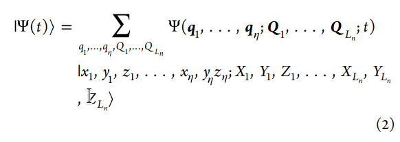
in the momentum representation,

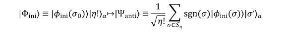
Initial Wave Function

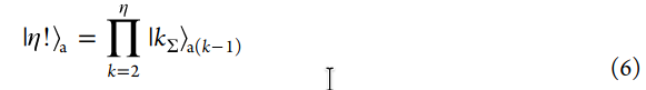
Antisymmetric States
-
preparation of the ancillae to the k-sequence state, or the $ k_{\Sigma} state
-
shuffling.

Mixed State of Energy Configurations.
thermal states
Time Evolution
Suzuki−Trotter decomposition.

with B.O.

Designed Circuits
parameters
Design Examples
Four simulator configurations:
- a basic one dimensional configuration with a 3-bit coordinate, one electron, one nucleus, and one initial wave function (d = 1, n = 3, η = 1, Ln = 1, NE = 1)
- the first example with two dimensions instead of one (d = 2, n = 4, η = 1, Ln = 1, NE = 1)
- a one-dimensional configuration with four electrons (d = 1, n = 2, η = 4, Ln = 1, NE =1)
- a one-dimensional configuration with two electrons, with four wave functions in the initial mixed state (d = 1, n = 2, η = 2, Ln = 1, NE = 4).
Example 1


uses a simple absolute value gate instead of a sequence of gates to calculate the norm for the distance between the electron and the nucleus.
The top six lines are qubits for the coordinate bits.
The lower 13 lines with labels tmpn are temporary qubits.
state preparation gate,
the circuit consists of nested time-evolution loops. Outer loop operates with nucleus scale time steps and the inner loop operates with electron scale time steps.
The first gate inside the inner loop is the $ \theta_{ep} gate, which calculates the electron−electron and electron− nucleus potential energy terms
electron kinetic energy (K.E.) time evolution gate,
nQFT,
paper fig2: preparation
with one eletron, the permutations to build the Slater determinant are not present.
The three-bit state embedding gate, emb(3), is applied to each of the two coordinate registers, e0x and n0x
recursive structures of those two gates are illustrated in Figure 2C through H.
paper fig3
Electron P.E. time evolution gate,
using 19 qubits
IQFT is independently applied to each of the coordinate bit sets.
paper fig4
K.E. time evolution gate, Θek, is shown in Figure 4A.
nQFT† in 4B
example 2
with two-dim H
paper fig5
The overall bit count is 36, number of coordinate qubits is 8,
gates
ssub (signed subtraction) gates
ssquare (signed square) gate for the x and y coordinates.
uaddv (unsigned adder) gate,
sqrt (square root) gate.
udiv (unsigned divide) gate takes the inverse of the result of the sqrt gate.
witth same overall circuit
difference is
example 3
paper fig6: overall circuit
a model with multiple electrons and introduces anti-symmetrization
a one-dimensional model with four electrons and one nucleus, using two-bit coordinates, beryllium atom
The total number of qubits is 28
paper fig7
The SD gate, Ψsd, is shown in Figure 7A.
unary-coded permutation gate
A gate sequence of XZX is inserted before the shuffling gates when η is even to cancel an artificial global phase π added in the circuit
The input to XZX is |0⟩, so the XZX sequence adds a global phase of π.
paper fig9
The unary-coded conditional shuffling gate
each shuffle gate adds a global phase of π. When η is odd, an even number of π phases are added so they cancel out. In contrast, when η is even, an odd number of π phases are added so the phase remains.
just for debugging since global phase does not affect the result of the circuit
paper fig8
sequence preparation gate kuΣ for k = 2, 3, and 4 is shown in Figure 8.
A CNOT gate follows each
so, only one of the output qubits is |1⟩; the other qubits are |0⟩.
paper fig10
Figure 10 shows the binary-coding-based permutation gate
paper fig11
Figure 11 shows the binary-coded sequence preparation gate
paper fig12
Figure 12 shows binary-coded conditional shuffling gates,
Example 4
a model of excitation, thereby making chemical reactions possible.
a model with one dimension, 2-bit coordinates, two electrons, one nucleus, and four sets of initial wave functions.
paper fig13
general state preparation gate, Ψg, (Figure 13 A
The configuration preparation gate, ρ (Figure 13B)
Evaluation of the Qubit Count for Different Model Sizes
paper fig14
using Born−Oppenheimer approximation, the qubits used to store the nuclei coordinates are omitted,
DESIGN OF THE IMPLEMENTATION
- Program Structure
- Arithmetic Component
- Qubit Heap Component
- AST Component
- Scope Class
- Simulator Gate Component
Details
Program Structure
four component
- arithmetic component: provides functions to build circuits
- qubit heap component: maintains a heap or pool
- abstract syntax tree component: provides node classes for a tree structure that represents a calculation of a formula
- simulator gates component: provides a high-level interface on top of the arithmetic component.
Scope Class
to create the node objects and keep track of them.
scope object provides methods to create leaf nodes
Simulator Gate Component
top-level component of the structure of the simulator program
- Wave Function Preparation Gates.
- Time Evolution Gates.
Verification/Testing
The Aer simulator implements several simulation methods; the basic “statevector” method was used.7 This method allows inspection of the state vector data, which is impossible with an actual quantum computer.
- Verification of Arithmetic Gates
- Verification of Abstract Syntax Trees.
- Verification of Time-Evolution Calculation
- Verification of Initial State Preparation
Details
Arithmetic Gates
The input data used in the code in the test suite is a single state, not a superposition because when an unexpected output is produced due to a bug
we prepared the input qubits in a superposition of all possible input values. The program then ran the circuit on a simulator and extracted the state vector from the simulator. We checked each term of the state vector whether it has a nonzero amplitude
From the superposition state, we extracted only the values which is bigger than ε,which ε is chosen to be large enough to filter out noise entries.
paper fig 24 and paper fig25 plot resluts
Abstract Syntax Trees.
tested by creating a minimal tree for each operation type and having the tree generate the quantum circuit, which was then run, and the resulting state vector was inspected.
Time-Evolution Calculation
tested by running them on tailored wave functions
verified the correctness of the circuit by inspecting the phase shift of each element of the resulting state vector.
Initial State Preparation
general-state preparation gate, Ψg. This gate has two subcomponents: the SD preparation gate,
Ψsd gate is further decomposed into the state embedding gate, emb(n), and the permutation gate,
Ψsd gate inspecting the state vector by extracting the wave function entangled with each value of register set a. Permutation gate make amplitude values inverted.
Final
Heap component that we designedwas confirmed to be effective.
The simulator circuit has the structure shown in paper fig 23, which illustrates more than 15 examples of gate usage. Each gate invocation is accompanied by target qubit passing, where the temporary qubit count must be determined. The ability to calculate the number of temporary qubits automatically was found valuable.
CONCLUSIONS
We have implemented and verified a quantum circuit generator program that can construct grid-based first quantization chemical simulator circuits.
limitations
- required qubit count exceeded the treatable one.
- built basic circuit, although various improvements have been proposed.
- had not yet evaluated gate count or circuit depth in our software.